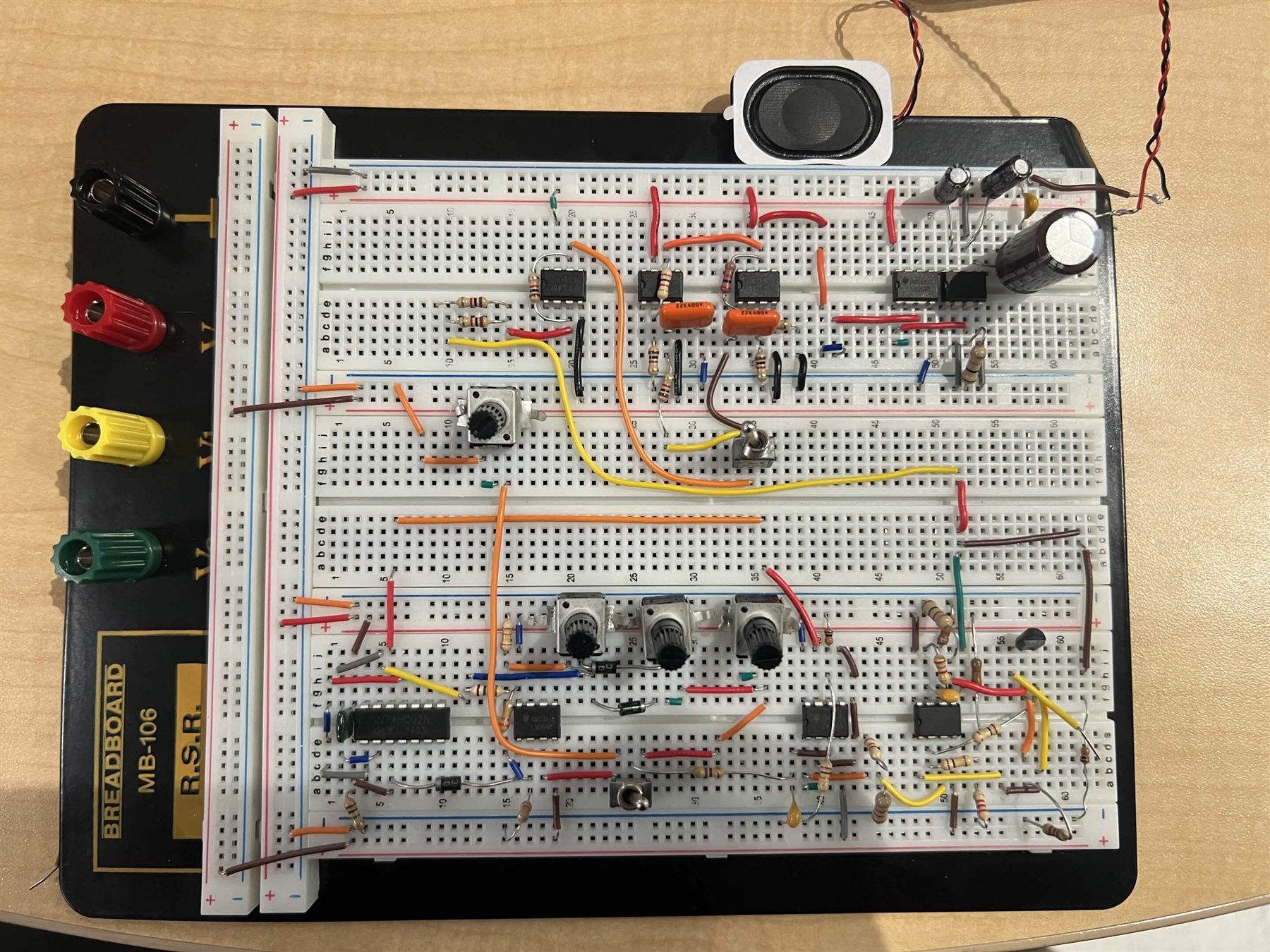
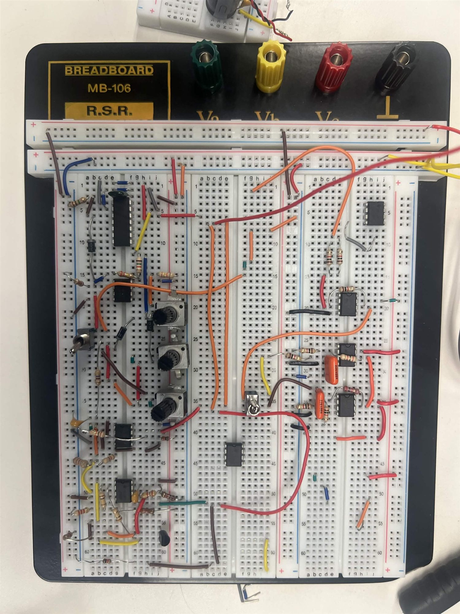
A polyphonic analog synthesizer built across two breadboards with zero
microcontrollers. Three voices are summed through a UA741 op-amp, shaped by
an ADSR envelope driving JFET VCAs, filtered through a switchable HP/LP stage,
and amplified by an LM386 into an 8 Ω 2 W speaker.
// Clean rewire · full synth on a single breadboard
Voices
3 polyphonic summed via UA741
Filter
HP / LP switchable -3 dB at 500 Hz · 10 dB gain
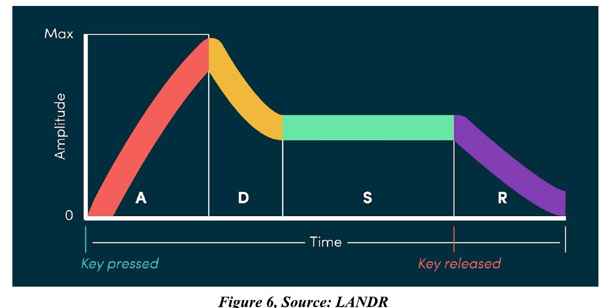
Envelope
ADSR 74LS02 SR latch · 2N5457 VCA
Output
LM386 → 8 Ω 2 W ∼0.5 W typical, 6.25 W theoretical max
// 01 — Problem
A musical instrument made entirely of op-amps.
The brief was to build an analog synthesizer that produces distinct musical pitches
when keys are pressed, mixes those voices, filters them in real time, and amplifies
the result through a speaker — all without a microcontroller. Frequency comes
from RC products, polyphony comes from a summing op-amp, character comes from an
envelope generator and a filter, and loudness comes from a dedicated audio amp IC.
Design constraints
Low-voltage DC supply (9–12 V); dual ±12 V for op-amps
Analog electronics only — no microcontrollers or DSP
Op-amps used for mixing, filtering, and envelope/effects
Momentary push-button keys, like a real keyboard
Impedance-matched output to an 8 Ω 2 W speaker
Real-time tuning via potentiometers and switches
Must fit on 1–2 breadboards (forces a 3-key count)
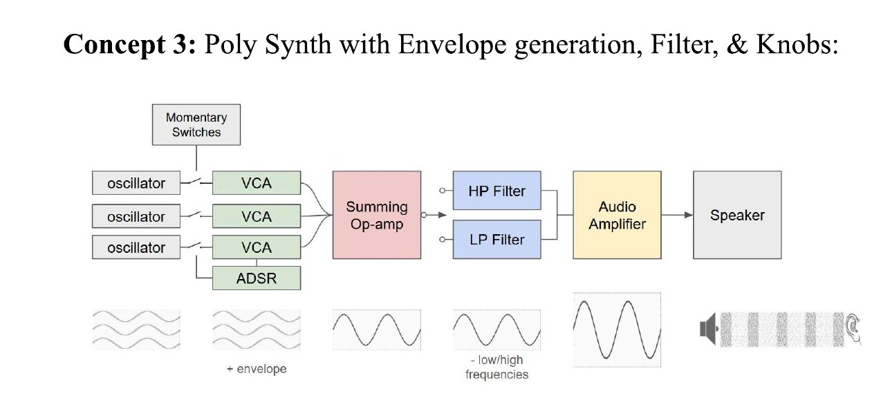
Design selection
Three concepts were scored 1–5 on sound variety, real-time control, and
harmonic capability: a mono synth with filter (3/15), a poly
synth with filter and knobs (11/15), and a poly synth with
ADSR + filter + knobs (15/15). The third concept won on every
axis, so the final build adds envelope shaping on top of polyphony and tunable
filtering.
// 02 — System Flow
From key press to shaped speaker output.
Each key gates a voice through a JFET VCA; the ADSR envelope decides how that
voice grows and fades over time. All three voices land at a summing op-amp, the
sum passes through an HP/LP filter, and the LM386 lifts the result up to speaker
level.
RC oscillators set the pitch
Each voice uses an op-amp RC oscillator where output frequency is set by f = 1/(R·C). Pitches follow twelve-tone equal temperament with A4 = 440 Hz, so a note n semitones from A4 sits at F = 440 · 2^(n/12).
Momentary keys trigger ADSR
Pressing a DPDT key starts the envelope: a capacitor charges through R_A (attack), partially discharges through R_D to a sustain voltage set by R_S, and releases through R_R when the key is let go. A 74LS02 NOR-gate SR latch with a comparator transitions the stages.
JFET VCA imprints the envelope
The DC envelope voltage drives a 2N5457 JFET biased in its ohmic region, varying its channel resistance and modulating the AC oscillator signal. The result is the same waveform with attack, decay, sustain, and release shaping baked in.
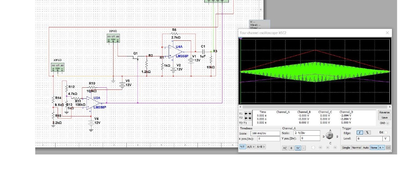
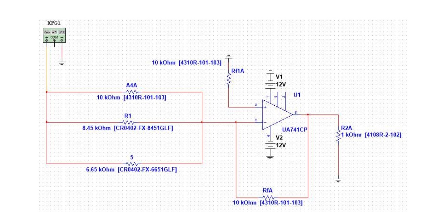
UA741 summing op-amp mixes voices
The three shaped voices feed an inverting summing amplifier — resistors 10 kΩ, 8.45 kΩ, and 6.65 kΩ into the virtual-ground node, with a 10 kΩ feedback. V_out = −R_f(V1/R1 + V2/R2 + V3/R3), dual ±12 V supply.
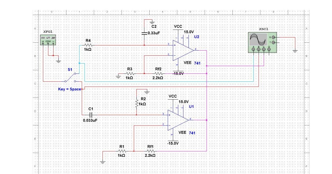
HP/LP filter trims the timbre
A dual op-amp first-order filter on the LM358 sits between the summer and the amp. An SPDT switch picks high-pass or low-pass; a potentiometer tunes the corner. Designed for −3 dB at 500 Hz with 10 dB gain — R_f = 2.2 kΩ, C = 0.33 µF.
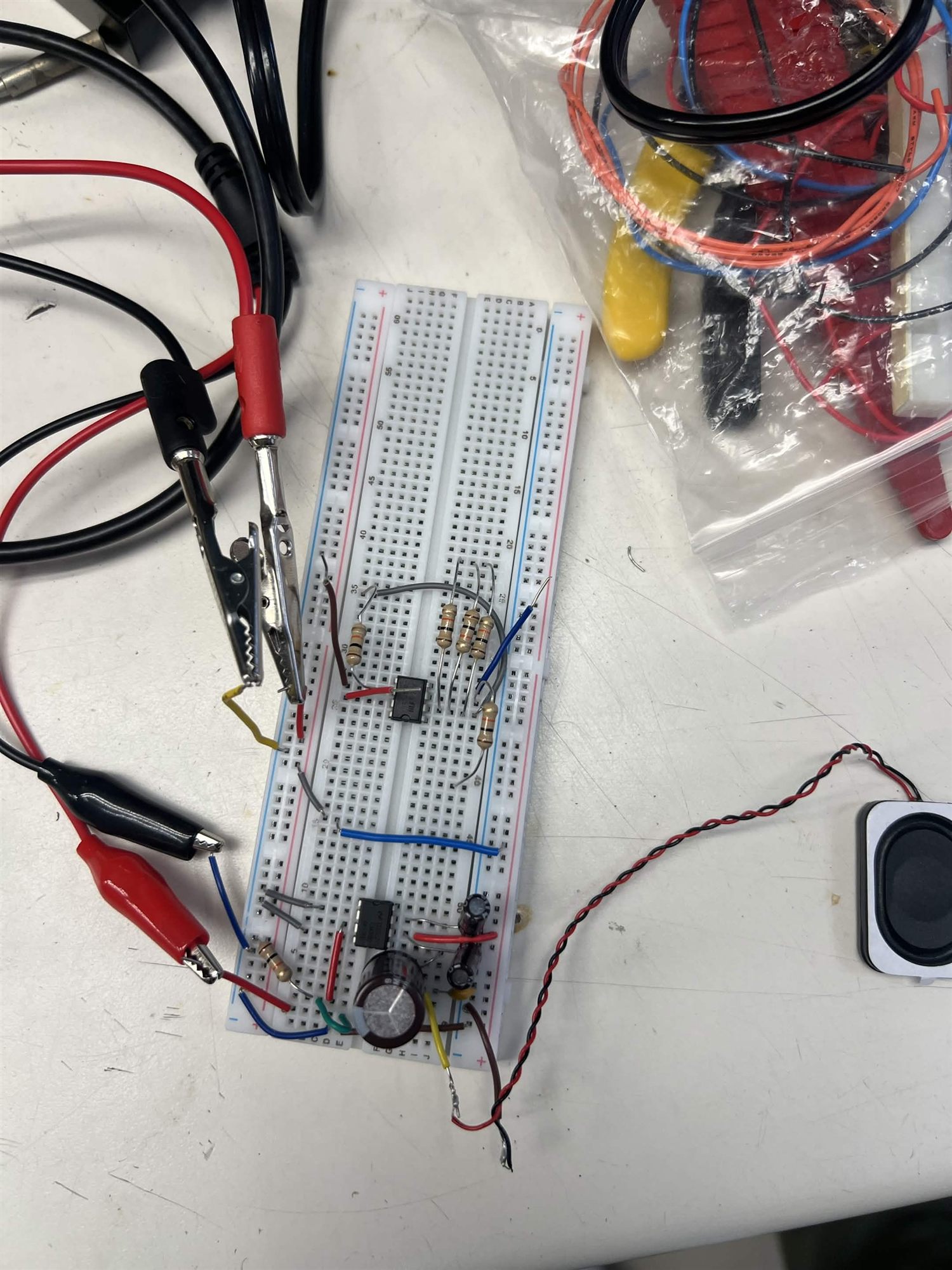
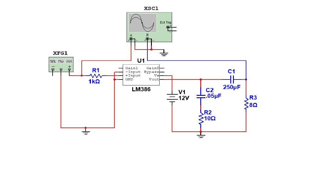
LM386 drives the speaker
The LM386 is wired for a gain of 200 to lift the small mixed signal to speaker level. At a 0.1 V input that's 20 V peak in theory; in practice the supply caps the swing — comfortable in the half-watt range into the 8 Ω 2 W speaker.
// 03 — Subsystems
Five analog stages, one signal path.
Voice oscillators
Each voice is an op-amp RC oscillator whose frequency comes from f = 1/(R·C). With C = 0.01 µF and target A4 = 440 Hz, R works out to 227 kΩ — resistors are sized per note from the twelve-tone formula.
ADSR envelope generator
R_A / R_D / R_S / R_R are potentiometers so attack, decay, sustain, and release are all tunable live. A capacitor C_Env stores the envelope state; a comparator + 74LS02 SR latch flips between charging and discharging paths when the key is pressed and released.
JFET VCA
A 2N5457 N-channel JFET runs in its ohmic region as a voltage-controlled resistor. The envelope's DC level varies the channel resistance, which scales the oscillator's AC signal — transferring envelope shaping onto an audio waveform.
UA741 summing op-amp
Inverting summer with input resistors 10 kΩ, 8.45 kΩ, and 6.65 kΩ (different values let each voice carry a different weight), 10 kΩ feedback to ground via the virtual short. Dual ±12 V rails keep peaks well clear of clipping.
HP / LP filter
Dual first-order filters built on a single LM358 dual op-amp. An SPDT switch routes the signal through either the high-pass or the low-pass leg; a potentiometer trims the corner frequency on the fly. Targeted: −3 dB at 500 Hz with 10 dB gain.
LM386 audio amplifier
Audio-amp IC dedicated to driving small speakers from a 4–12 V supply. Configured for a gain of 200 (Av = 200) with the LM386's standard input/decoupling network feeding the 8 Ω 2 W speaker. Frequency response ∼5 Hz to 250 kHz covers the audio band comfortably.
UA741 op-ampLM358 dual op-ampLM386 audio amp2N5457 JFET74LS02 NOR / SR latch1N4149 diodeDPDT momentary keysSPDT filter switchDual ±12 V supplyTwelve-tone equal temperamentMultisimBreadboard prototyping
// 04 — Validation & Math
Tuning by hand, verified on paper.
Because there's no firmware to print a value, every stage is validated either with
a Multisim simulation or with hand calculations against datasheet numbers, then
tuned in real time on the breadboard with the pots and the SPDT switch.
Filter design (HP & LP)
Target: 10 dB DC gain → 20·log(1 + R_f/R_1) = 10 dB → R_f/R_1 = 2.16
// UA741 summing op-amp · three voices, dual ±12 V
// HP/LP filter · SPDT switch picks the corner
// LM386 amp · A_v = 200 into 8 Ω speaker
// 06 — Outcome
A working synth with real-time character.
The finished synth plays three distinct pitches polyphonically, with attack/decay/
sustain/release shaping each note and a switchable filter trimming the timbre. Six
potentiometers and an SPDT switch on the front of the board mean a player can
sculpt the sound while pressing keys — the whole point of the design.
What worked
Building the LM386 amp on its own board first let us debug audio in isolation